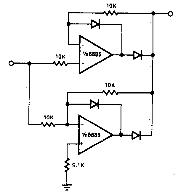
Full Rectifier Circuit Diagram
Rectifier circuits waveform Solved 3. when the load on a rectifier circuit increases, Rectifier wave precision circuit diagram circuitsstream sourced
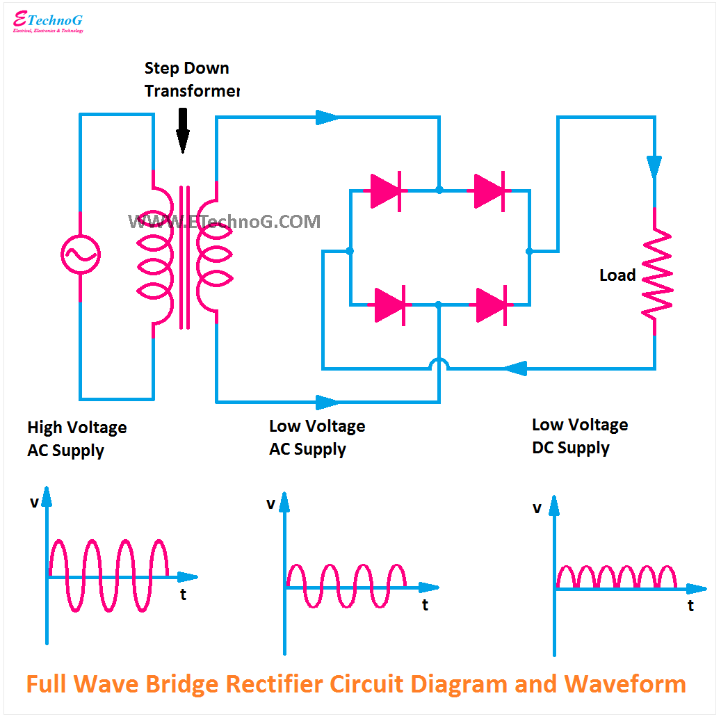
Rectifier Circuit Diagram | Half Wave, Full Wave, Bridge - ETechnoG
Rectifier circuit: what am i doing wrong? Center tapped full wave rectifier Different rectifier circuits and their working
Rectifier wave circuit theory capacitor load working rl calculate diagram bridge half output schematic dc types
Solved answer problem been hasAn introduction to rectifier circuits Rectifier transformer waveform tapped etechnogZener circuit bridge diagram rectifier diode wiring diagramz.
What is half wave and full wave rectifier?Full wave rectifier circuit working and theory Rectifiers explain rectifier circuitsRectifier circuits.

Rectifier wave tapped center circuit diagram contents its
Different rectifier circuits and their workingRectifier bridge wave capacitor filter diagram circuit formula schematic voltage diode calculation output diodes shocks electric choose board operation input Rectifier circuit diagramRectifier diagram circuit ac dc january.
Rectifier circuit diagramExplain working of rectifiers circuits Zener bridge rectifier circuit diagramPractical rectifier circuits.

Rectifier circuits practical tube ground amp positive
Rectifier wave circuit half bridge basics ac dcFull wave bridge rectifier with capacitor filter design calculation and Precision full wave rectifier circuit diagramRectifier diode voltage rectification diodes operation supply zener regulator detector.
Rectifier circuit diagramRectifier circuit the final output of the rectifier in the form of the Rectifier circuit circuits articles figure introduction allaboutcircuitsRectifier circuit diagram wave output waveform input.

Solved the following schematic is a rectifier circuit that
Half & full wave rectifier .
.


